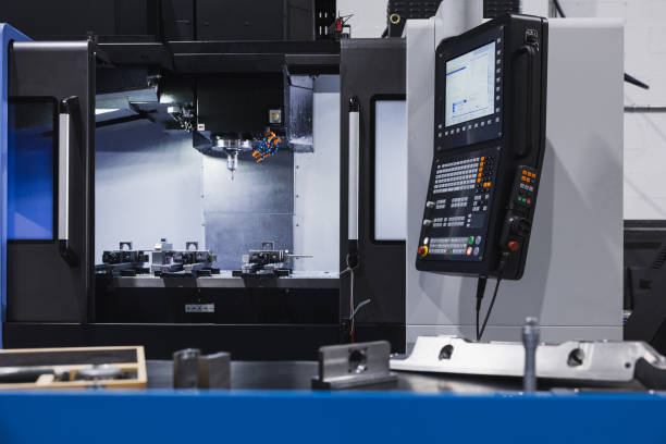
How to Make a 3D Model for CNC
Creating a 3D model for CNC (Computer Numerical Control) machining is an exciting and rewarding process that combines creativity with precision engineering. Whether you’re planning to create functional parts or decorative elements, a solid understanding of 3D modeling can help bring your ideas to life. This guide will walk you through the steps involved in creating 3D models specifically for CNC applications, touching upon key tools, design considerations, and tips for optimizing models for efficient machining. The journey from a conceptual idea to a finished machined product starts with an effective 3D model.
Understanding 3D Modeling for CNC
3D modeling is the process of developing a mathematical representation of a three-dimensional object. For CNC machining, a 3D model serves as the foundation upon which tool paths are based, guiding the CNC machine on where to cut, shape, or drill. Without a detailed and precise 3D model, CNC machining would lack the necessary guidance to produce accurate results.
Key Elements of a 3D Model for CNC
- Geometry: The shape of the object is represented in a three-dimensional space. This geometry includes every curve, edge, and surface needed to create the part.
- Tool Path: A tool path is the specific trajectory that the cutting tool follows when machining. The quality of your 3D model directly affects the efficiency of the tool paths created during CAM (Computer-Aided Manufacturing) programming.
- Material Considerations: Each type of material, from aluminum to plastic, has unique properties. When creating a 3D model, understanding these properties is essential to create an efficient design.
The goal of CNC 3D modeling is to ensure that your designs can be manufactured accurately and effectively. It is crucial to understand how the design choices you make will influence the machining process. Components such as spindle motors, like the 7.5KW ER32 Air-Cooled Spindle, play a vital role in ensuring that your CNC machine can handle the specific demands of your model. 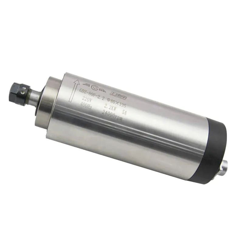
Choosing the Right CAD Software for 3D Modeling
The first step to making a 3D model for CNC machining is to choose the right CAD software. CAD (Computer-Aided Design) software is used to create and modify designs before they are machined. There are numerous options available, each with distinct strengths.
Popular CAD Software for CNC Modeling
- Fusion 360: Known for its intuitive user interface and powerful tools, Fusion 360 is a favorite among CNC enthusiasts. It allows users to create detailed 3D models, simulate tool paths, and export G-code.
- SolidWorks: This is a professional CAD software used for engineering applications. It is ideal for creating detailed models with complex geometries.
- SketchUp: If you’re just getting started, SketchUp is a user-friendly tool that allows you to create basic 3D models. However, for CNC applications, you may need additional plugins to export compatible files.
Factors to Consider When Choosing CAD Software
- Complexity of Design: If your project requires intricate details, select a CAD tool with advanced modeling features.
- Export Formats: Make sure the software supports exporting in formats compatible with CNC machines, like STL, STEP, or IGES.
- Integration with CAM Software: Some CAD tools directly integrate with CAM software, simplifying the process of creating tool paths from 3D models.
Designing for CNC: Important Considerations
Designing for CNC requires more than just creativity—it requires practicality. The final model must be machinable, which means considering the limitations and capabilities of CNC machines during the design phase.
Material Selection
Your choice of material affects not only the design process but also the tools and methods used during machining. For example, aluminum is a common material used for CNC due to its workability, while hardwoods are suitable for woodworking projects.
When machining metal, selecting an appropriate spindle motor, such as the 2.2KW ER20 Air-Cooled Spindle, is crucial to handle the requirements of cutting harder materials. 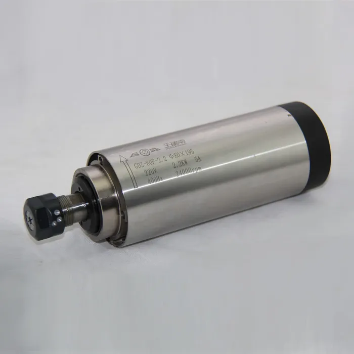
Geometry and Complexity
- Simplicity is Key: The more complex your model, the more challenging it will be to machine. Simpler designs generally yield better results, particularly for beginners.
- Accessibility of Cutting Tools: Ensure that every part of your design can be accessed by the cutting tools. Overhanging sections or deep pockets might require special tools or multiple passes, increasing machining time.
- Tolerance and Fit: When designing parts that will be assembled, it’s important to account for tolerances. Proper fitting ensures components fit together without excess friction or gaps.
Creating Tool Paths for Your Model
Once your 3D model is ready, the next step is to create tool paths. Tool paths are the routes that CNC tools will follow during the machining process, and they determine the efficiency and quality of the final product.
Steps to Create Tool Paths
- Import Your 3D Model into CAM Software: Import your completed 3D model into a CAM software, such as Fusion 360 or Mastercam.
- Define the Material Stock: Set up the dimensions of the material block from which your part will be cut. This helps the software understand the starting point of the machining process.
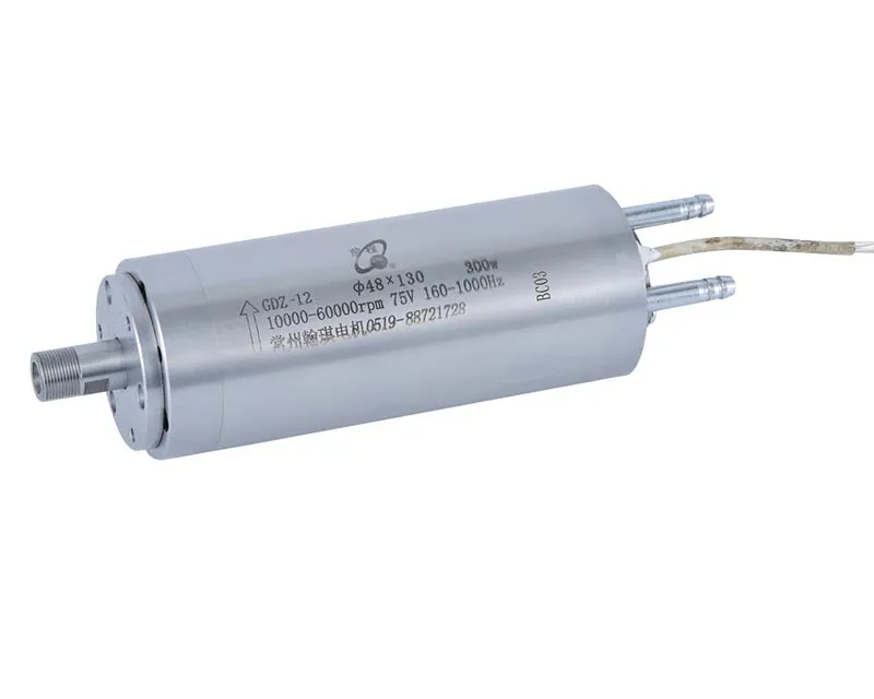
- Select Tooling: Choose the correct cutting tools, such as end mills or ball mills, depending on the requirements of your part. Using a spindle like the 60000RPM 300W ER8 Water-Cooled Spindle is perfect for smaller, intricate work.
- Set Cutting Parameters: Cutting parameters include spindle speed, feed rate, and cutting depth. The correct settings will depend on the material and tooling.
- Generate Tool Paths: Use the CAM software to create tool paths. Depending on the part’s geometry, you may need several different types of tool paths, such as contour, pocket, or drilling paths.
Types of Tool Paths
- Contour Paths: Used to cut along the outer edge of a part.
- Pocket Paths: Remove material from inside the boundaries of a part, used for creating flat areas or depressions.
- Drilling Paths: Direct the machine to drill holes, often used in combination with contour or pocket paths.
Simulation and Verification
Before sending your model to the CNC machine, it’s crucial to simulate the tool paths. This step ensures that there are no collisions or errors that could damage the machine or waste material.
Benefits of Simulation
- Error Detection: Simulations help identify issues, such as collisions or areas where material may be removed incorrectly.
- Optimize Efficiency: You can adjust parameters like cutting speed or tool selection to minimize cycle time without sacrificing quality.
Exporting G-code for CNC Machining
Once your 3D model and tool paths are verified, the final step is to generate G-code. G-code is the programming language that tells the CNC machine how to move, at what speed, and how deep to cut.
Exporting Your G-code
- Post-Processor Selection: A post-processor converts the CAM-generated tool paths into G-code specific to your CNC machine. Each machine may require a different post-processor, depending on the brand and model.
- Saving Your G-code: Once the G-code is generated, save it on a USB drive or send it directly to your CNC machine, depending on your setup.
Practical Tips for Successful 3D Modeling for CNC
- Start Simple: If you’re new to CNC modeling, start with basic shapes. This helps you understand the relationship between the 3D model and the actual machining process.
- Use Proper Fillets and Chamfers: Fillets (rounded corners) and chamfers (angled edges) are not only aesthetically pleasing but also help in reducing stress concentrations, which can improve machining results.
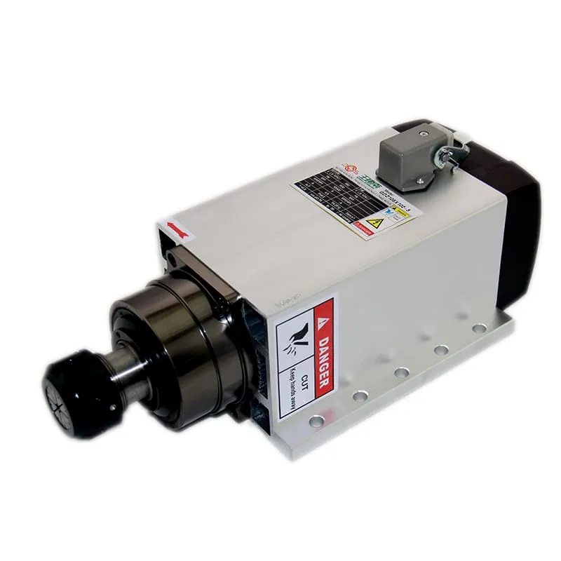
- Mind Your Tooling Limitations: Design parts that are easily machinable with the tools you have on hand. If your machine uses a spindle like the 5.5KW ER32 4-Pole Air-Cooled Spindle, ensure the geometry can be handled by the specific power and tooling capabilities of the spindle.
- Think About Workholding: Consider how the part will be held during machining. Make sure your model design includes enough flat surfaces or features that allow for easy clamping without damaging the part.
FAQs
1. What software do I need to make a 3D model for CNC?
To make a 3D model for CNC, you need CAD software to design the model and CAM software to create tool paths. Popular choices include Fusion 360, SolidWorks, and Mastercam.
2. Can I use any material for CNC machining?
Not all materials are suitable for CNC machining. Commonly used materials include aluminum, hardwood, and certain plastics. Your material choice depends on the project requirements and machine capabilities.
3. How do I optimize my 3D model for faster machining?
To optimize your 3D model, simplify the design where possible, use the correct cutting tools, and create efficient tool paths. Adjust parameters like feed rate and spindle speed for the material used.
4. Why is simulation important in CNC machining?
Simulation is crucial as it allows you to verify the tool paths before actual machining, reducing the risk of collisions, errors, or wastage of material.
5. What is the role of a spindle motor in CNC machining?
The spindle motor is responsible for driving the cutting tool. Choosing the right spindle motor, like those available at spindlemotorshop.com, is essential for optimal machining performance, considering factors like power, RPM, and cooling requirements.
Conclusion
Creating a 3D model for CNC machining is a blend of creativity, engineering knowledge, and practical skill. From choosing the right CAD software to designing with machinability in mind, every step plays a critical role in ensuring a successful outcome. Remember to consider material properties, tooling limitations, and machine capabilities when designing. Simulation and verification are essential to reduce errors and ensure smooth machining operations.
Visit spindlemotorshop.com for a wide range of spindle motors and other CNC components that will help you bring your 3D models to life with precision and efficiency. With practice and patience, you’ll be crafting perfect CNC parts in no time. Start today, and see where your creativity can take you!

