Creating a CNC program for milling involves using Computer Numerical Control (CNC) to automate machining tasks that are traditionally done by hand. The use of CNC machines is essential in modern manufacturing to ensure precision, repeatability, and efficiency. This guide will explain how to write a CNC milling program, breaking down the steps, providing practical tips, and offering an in-depth understanding of various codes and commands required to achieve the desired output.
Understanding CNC Programming
What is CNC Programming?
CNC programming is the process of writing commands, also known as G-code, that a CNC machine reads to execute specific movements. The programming dictates every detail of how the machine will cut, move, or drill to shape a workpiece into the desired form. CNC milling, in particular, uses rotating cutting tools to remove material from a workpiece to create a specified geometry.
In CNC programming, every tool movement, spindle speed, feed rate, and function is controlled through precise G-code instructions. The ultimate goal is to translate the CAD (Computer-Aided Design) drawing into a set of machine-readable instructions.
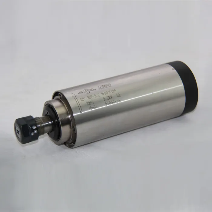
Internal Link: Explore our 2.2KW ER20 Air-Cooled Spindle to improve the efficiency of your milling machine.
Key Components of CNC Programming
1. G-Code and M-Code
- G-Code: The primary language used to control CNC machines. It includes commands like G00 (rapid movement), G01 (linear feed movement), G02 (clockwise arc), etc. G-codes specify the path that the tool must take.
- M-Code: M-codes are used for miscellaneous functions like turning on the coolant or stopping the spindle. Examples include M03 (spindle start) and M30 (program end).
These codes form the backbone of any CNC milling program. Each line, or block, of code represents a specific machine movement or action.
2. Coordinate System
CNC milling relies on a coordinate system to define the position of the cutting tool relative to the workpiece. The most commonly used system is G54, which sets the workpiece zero point. Additional commands such as G17 define the active plane (XY plane), and G90 sets absolute positioning mode.
- Work Coordinate System (WCS): Defined by G54, G55, etc., to determine where the machine zero is relative to the workpiece.
- Tool Length Compensation (TLC): G43 is used to account for the tool length, which ensures the tool tip is correctly positioned.
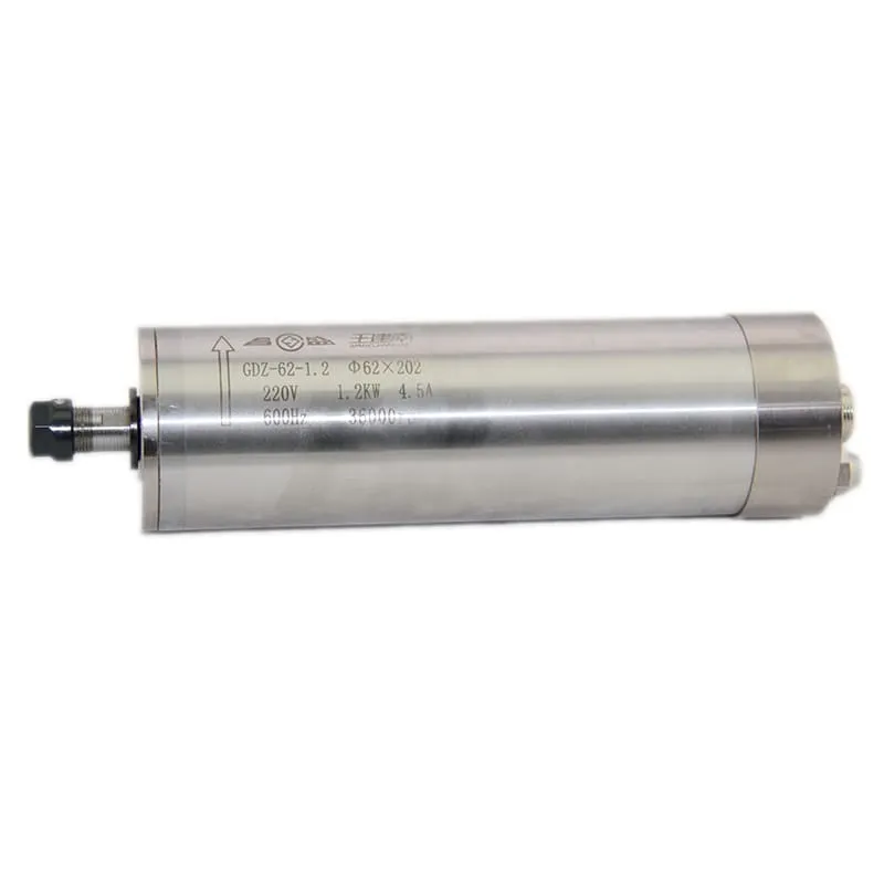
Internal Link: Enhance your accuracy with our 60000RPM 1.2KW ER11 Water-Cooled Spindle for smooth and precise operations.
Step-by-Step Guide to Writing a CNC Milling Program
Step 1: Define the Coordinate System
The first step in writing a CNC program is defining the coordinate system. Typically, you’ll begin with G17 to set the active plane (XY), followed by G54 to set the workpiece origin.
- G17 sets the XY plane as active.
- G54 sets the work offset, or zero point.
- G90 is used for absolute positioning.
Step 2: Start the Spindle and Set the Tool
- Use M06 to select the appropriate tool.
- M03 starts the spindle, and S1000 sets the spindle speed to 1000 RPM.
- T1 represents Tool 1.
- M06 is a tool change command.
- M03 starts the spindle, and S1000 sets the spindle speed.
Step 3: Move to the Safe Start Position
The machine must move to a safe position before starting the cut. G00 is used for rapid movement.
- G00 moves the tool quickly to the starting point at X0, Y0, and a safe height of Z5 mm above the workpiece.
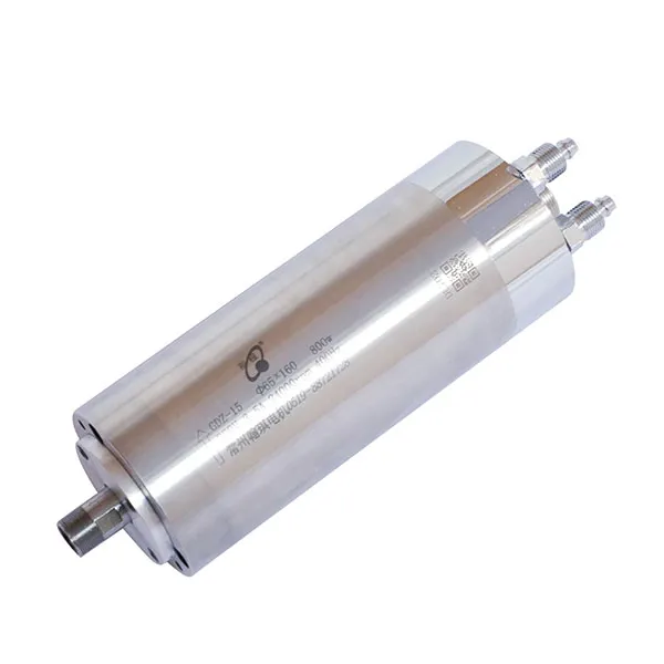
Internal Link: Ensure your CNC machine’s efficiency with our 24000RPM 800W ER11 Water-Cooled Spindle.
Milling Operations and Cycles
1. Linear Interpolation (G01)
Linear interpolation (G01) is used for cutting straight lines. You need to define the feed rate (F), which is the speed at which the tool advances.
- G01 tells the machine to cut in a straight line to X50 Y50.
- F100 sets the feed rate to 100 mm/min.
2. Drilling Cycle (G81)
Drilling is done using G81, which is a canned cycle that helps automate repetitive drilling operations.
- G81 starts the drilling cycle.
- X10 Y10 are the coordinates for the hole location.
- Z-15 sets the drilling depth.
- R5 is the retract height, and F150 sets the feed rate.
3. Peck Drilling Cycle (G83)
G83 is a peck drilling cycle, useful for deeper holes that require clearing chips periodically. The tool moves down in increments, retracting each time to clear debris.
- G83 initiates the peck drilling cycle.
- Q5 defines the peck depth.
- Z-25 is the total depth, and F100 sets the feed rate.
Pro Tip: Peck drilling is essential for deep holes, preventing the buildup of heat and ensuring smooth chip removal.
Tool Length Compensation and Feed Rate Control
Tool Length Compensation (G43)
Tool length compensation is crucial to ensure that the tip of the tool reaches the correct position. G43 is often followed by H, which indicates the tool length offset.
- G43 activates tool length compensation.
- H01 refers to the tool offset value for the tool currently in use.
- Z10 sets the position, taking into account the length of the tool.
Feed Rate Control
The feed rate (F) dictates how quickly the cutting tool advances through the material. It varies depending on the type of material, the tool used, and the desired surface finish.
- Higher Feed Rates: Suitable for softer materials like aluminum or wood.
- Lower Feed Rates: Ideal for hard materials like steel, ensuring precision and reducing tool wear.
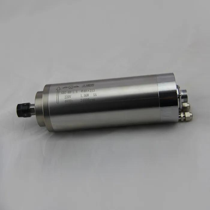
Internal Link: Upgrade your CNC setup with our 24000RPM 1.5KW ER16 Water-Cooled Spindle for enhanced performance.
Canned Cycles for Milling
1. Face Milling Cycle
Face milling involves machining a large, flat surface, usually to prepare the workpiece for subsequent operations. The G12 and G13 codes are often used for circular face milling.
- G13 indicates a counter-clockwise circular path.
- I50 J50 specify the diameter of the circle, and Z-1 is the depth.
- F150 sets the feed rate.
2. Boring Cycle (G85)
The boring cycle (G85) allows for precise internal enlargements of pre-existing holes. The tool feeds to the specified depth and retracts without rapid movement.
- G85 initiates the boring cycle.
- X30 Y30 are the coordinates for the boring operation.
- Z-20 sets the boring depth, and F100 is the feed rate.
3. Tapping Cycle (G84)
For threading holes, G84 is the tapping cycle, which moves the tool down while rotating to form threads inside a hole.
- G84 starts the tapping cycle.
- Z-10 sets the tapping depth, and F50 is the feed rate synchronized with the spindle rotation.
Finalizing the Program
Program End (M30)
Once all milling operations are complete, the program must be concluded properly. M30 is used to end the program and reset the machine for the next run.
- G00 Z10 moves the tool to a safe height.
- G00 X0 Y0 returns to the home position.
- M05 stops the spindle.
- M30 ends the program.
Some tips for Efficient CNC Programming
1. Use Subprograms for Repeated Patterns
Subprograms can simplify repetitive operations, reducing program length and making it easier to troubleshoot. Use M98 to call a subprogram.
2. Optimize Tool Changes
Minimize tool changes by grouping operations that use the same tool. This helps reduce cycle time and improve efficiency.

